Thursday, October 29, 2009

First Impressions


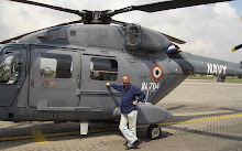
Here’s what we know so far by visually observing the crash of the Ecuadorian Air Force-owned Dhruv ALH at Quito on October 27: of the three Dhruv ALHs flying over an air base during celebrations to mark the 89th anniversary of the air force, one of them apparently swung 90 degrees and started losing altitude. As the video clip of the incident shows, the two-man aircrew who are in all probability highly experienced aviators, instinctively resorted to the autorotation technique (the only available option) to regain control and to their credit it must be said that they did succeed in slowing the rate of descent, although within the available 8 seconds, they could not stabilise the helicopter, which in turn led to a half-controlled descent and touchdown, with the stricken Dhruv ALH coming to rest on its portside, with the two-man aircrew managing to leave the helicopter by themselves after the crash before being taken to Quito's Military Hospital. The video clipping also showed the Dhruv ALH’s main rotor blades and tail rotor blades functioning, but not enough to indicate if the tail-rotor hub and tail-rotor shaft were in a fully functional state. Based purely on the available video clipping, it would seem that:

• The ill-fated Dhruv PROBABLY suffered from a sudden loss of power in either one of its twin Ardiden-1H (Shakti) engines, jointly built by HAL and Turbomeca. But catastrophic failure of both engines or failure of both the LH and RH sides of the main gearbox (MGB) can be ruled out. It is also PROBABLE that either one of the two fuel supply tanks (which supply fuel independently to the two engines) was starved of fuel-flow from the the Dhruv ALH’s three main fuel tanks, which house the pumps required for ensuring the fuel-flow to the fuel supply tanks.

• The above two probabilities PROBABLY contributed to the sudden reduction of supply of power to the tail-rotor gearbox via the tail-rotor drive shaft, resulting in the helicopter veering off to the left while losing altitude at the same time.

The only saving grace then, and the only available option for the aircrew then was to resort to the autorotation technique, which they did and that is probably the only reason they were fortunate enough to survive to fly again in future. Full marks to them!—Prasun K. Sengupta

I am enclosing below all the FAR Part 29standards that the Dhruv ALH complies with. FAR Part 29: Airworthiness Standards: Transport Category Rotorcraft
Federal Aviation Regulations Subpart A - General
o Sec. 29.1 - Applicability.
o Sec. 29.2 - Special retroactive requirements.Subpart B - Flight
o Sec. 29.21 - Proof of compliance.
o Sec. 29.25 - Weight limits.
o Sec. 29.27 - Center of gravity limits.
o Sec. 29.29 - Empty weight and corresponding center of gravity.
o Sec. 29.31 - Removable ballast.
o Sec. 29.33 - Main rotor speed and pitch limits.
o Sec. 29.45 - General.
o Sec. 29.49 - Performance at minimum operating speed.
o Sec. 29.51 - Takeoff data: general.
o Sec. 29.53 - Takeoff: Category A.
o Sec. 29.55 - Takeoff decision point (TDP): Category A.
o Sec. 29.59 - Takeoff path: Category A.
o Sec. 29.60 - Elevated heliport takeoff path: Category A.
o Sec. 29.61 - Takeoff distance: Category A.
o Sec. 29.62 - Rejected takeoff: Category A.
o Sec. 29.63 - Takeoff: Category B.
o Sec. 29.64 - Climb: General.
o Sec. 29.65 - Climb: All engines operating.
o Sec. 29.67 - Climb: One engine inoperative (OEI).
o Sec. 29.71 - Helicopter angle of glide: Category B.
o Sec. 29.75 - Landing: General.
o Sec. 29.77 - Landing Decision Point (LDP): Category A.
o Sec. 29.79 - Landing: Category A.
o Sec. 29.81 - Landing distance: Category A.
o Sec. 29.83 - Landing: Category B.
o Sec. 29.85 - Balked landing: Category A.
o Sec. 29.87 - Height-velocity envelope.
o Sec. 29.141 - General.
o Sec. 29.143 - Controllability and maneuverability.
o Sec. 29.151 - Flight controls.
o Sec. 29.161 - Trim control.
o Sec. 29.171 - Stability: general.
o Sec. 29.173 - Static longitudinal stability.
o Sec. 29.175 - Demonstration of static longitudinal stability.
o Sec. 29.177 - Static directional stability.
o Sec. 29.181 - Dynamic stability: Category A rotorcraft.
o Sec. 29.231 - General. o Sec. 29.235 - Taxiing condition.
o Sec. 29.239 - Spray characteristics.
o Sec. 29.241 - Ground resonance.
o Sec. 29.251 - Vibration.Subpart C - Strength Requirements
o Sec. 29.301 - Loads.
o Sec. 29.303 - Factor of safety.
o Sec. 29.305 - Strength and deformation.
o Sec. 29.307 - Proof of structure.
o Sec. 29.309 - Design limitations.
o Sec. 29.321 - General.
o Sec. 29.337 - Limit maneuvering load factor.
o Sec. 29.339 - Resultant limit maneuvering loads.
o Sec. 29.341 - Gust loads.
o Sec. 29.351 - Yawing conditions.
o Sec. 29.361 - Engine torque.
o Sec. 29.391 - General.
o Sec. 29.395 - Control system.
o Sec. 29.397 - Limit pilot forces and torques.
o Sec. 29.399 - Dual control system.
o Sec. 29.411 - Ground clearance: tail rotor guard.
o Sec. 29.427 - Unsymmetrical loads.
o Sec. 29.471 - General.
o Sec. 29.473 - Ground loading conditions and assumptions.
o Sec. 29.475 - Tires and shock absorbers.
o Sec. 29.477 - Landing gear arrangement.
o Sec. 29.479 - Level landing conditions.
o Sec. 29.481 - Tail-down landing conditions.
o Sec. 29.483 - One-wheel landing conditions.
o Sec. 29.485 - Lateral drift landing conditions.
o Sec. 29.493 - Braked roll conditions.
o Sec. 29.497 - Ground loading conditions: landing gear with tail wheels.
o Sec. 29.501 - Ground loading conditions: landing gear with skids.
o Sec. 29.505 - Ski landing conditions.
o Sec. 29.511 - Ground load: unsymmetrical loads on multiple-wheel units.
o Sec. 29.519 - Hull type rotorcraft: Water-based and amphibian.
o Sec. 29.521 - Float landing conditions.
o Sec. 29.547 - Main and tail rotor structure.
o Sec. 29.549 - Fuselage and rotor pylon structures.
o Sec. 29.551 - Auxiliary lifting surfaces.
o Sec. 29.561 - General.
o Sec. 29.562 - Emergency landing dynamic conditions.
o Sec. 29.563 - Structural ditching provisions.
o Sec. 29.571 - Fatigue evaluation of structure.Subpart D - Design and Construction
o Sec. 29.601 - Design.
o Sec. 29.602 - Critical parts.
o Sec. 29.603 - Materials.
o Sec. 29.605 - Fabrication methods.
o Sec. 29.607 - Fasteners.
o Sec. 29.609 - Protection of structure.
o Sec. 29.610 - Lightning and static electricity protection.
o Sec. 29.611 - Inspection provisions.
o Sec. 29.613 - Material strength properties and design values.
o Sec. 29.619 - Special factors.
o Sec. 29.621 - Casting factors.
o Sec. 29.623 - Bearing factors.
o Sec. 29.625 - Fitting factors.
o Sec. 29.629 - Flutter and divergence.
o Sec. 29.631 - Bird strike.
o Sec. 29.653 - Pressure venting and drainage of rotor blades.
o Sec. 29.659 - Mass balance.
o Sec. 29.661 - Rotor blade clearance.
o Sec. 29.663 - Ground resonance prevention means.
o Sec. 29.671 - General.
o Sec. 29.672 - Stability augmentation, automatic, and power-operated systems.
o Sec. 29.673 - Primary flight controls.
o Sec. 29.674 - Interconnected controls.
o Sec. 29.675 - Stops.
o Sec. 29.679 - Control system locks.
o Sec. 29.681 - Limit load static tests.
o Sec. 29.683 - Operation tests.
o Sec. 29.685 - Control system details.
o Sec. 29.687 - Spring devices.
o Sec. 29.691 - Autorotation control mechanism.
o Sec. 29.695 - Power boost and power-operated control system.
o Sec. 29.723 - Shock absorption tests.
o Sec. 29.725 - Limit drop test.
o Sec. 29.727 - Reserve energy absorption drop test.
o Sec. 29.729 - Retracting mechanism.
o Sec. 29.731 - Wheels.
o Sec. 29.733 - Tires.
o Sec. 29.735 - Brakes.
o Sec. 29.737 - Skis.
o Sec. 29.751 - Main float buoyancy.
o Sec. 29.753 - Main float design.
o Sec. 29.755 - Hull buoyancy.
o Sec. 29.757 - Hull and auxiliary float strength.
o Sec. 29.771 - Pilot compartment.
o Sec. 29.773 - Pilot compartment view.
o Sec. 29.775 - Windshields and windows.
o Sec. 29.777 - Cockpit controls.
o Sec. 29.779 - Motion and effect of cockpit controls.
o Sec. 29.783 - Doors.
o Sec. 29.785 - Seats, berths, litters, safety belts, and harnesses.
o Sec. 29.787 - Cargo and baggage compartments.
o Sec. 29.801 - Ditching.
o Sec. 29.803 - Emergency evacuation.
o Sec. 29.805 - Flight crew emergency exits.
o Sec. 29.807 - Passenger emergency exits.
o Sec. 29.809 - Emergency exit arrangement.
o Sec. 29.811 - Emergency exit marking.
o Sec. 29.812 - Emergency lighting.
o Sec. 29.813 - Emergency exit access.
o Sec. 29.815 - Main aisle width.
o Sec. 29.831 - Ventilation.
o Sec. 29.833 - Heaters.
o Sec. 29.851 - Fire extinguishers.
o Sec. 29.853 - Compartment interiors.
o Sec. 29.855 - Cargo and baggage compartments.
o Sec. 29.859 - Combustion heater fire protection.
o Sec. 29.861 - Fire protection of structure, controls, and other parts.
o Sec. 29.863 - Flammable fluid fire protection.
o Sec. 29.865 - External loads.
o Sec. 29.871 - Leveling marks.
o Sec. 29.873 - Ballast provisions.Subpart E - Powerplant
o Sec. 29.901 - Installation.
o Sec. 29.903 - Engines.
o Sec. 29.907 - Engine vibration.
o Sec. 29.908 - Cooling fans.
o Sec. 29.917 - Design.
o Sec. 29.921 - Rotor brake.
o Sec. 29.923 - Rotor drive system and control mechanism tests.
o Sec. 29.927 - Additional tests.
o Sec. 29.931 - Shafting critical speed.
o Sec. 29.935 - Shafting joints.
o Sec. 29.939 - Turbine engine operating characteristics.
o Sec. 29.951 - General.
o Sec. 29.952 - Fuel system crash resistance.
o Sec. 29.953 - Fuel system independence.
o Sec. 29.954 - Fuel system lightning protection.
o Sec. 29.955 - Fuel flow.
o Sec. 29.957 - Flow between interconnected tanks.
o Sec. 29.959 - Unusable fuel supply.
o Sec. 29.961 - Fuel system hot weather operation.
o Sec. 29.963 - Fuel tanks: general.
o Sec. 29.965 - Fuel tank tests.
o Sec. 29.967 - Fuel tank installation.
o Sec. 29.969 - Fuel tank expansion space.
o Sec. 29.971 - Fuel tank sump.
o Sec. 29.973 - Fuel tank filler connection.
o Sec. 29.975 - Fuel tank vents and carburetor vapor vents.
o Sec. 29.977 - Fuel tank outlet.
o Sec. 29.979 - Pressure refueling and fueling provisions below fuel level.
o Sec. 29.991 - Fuel pumps.
o Sec. 29.993 - Fuel system lines and fittings.
o Sec. 29.995 - Fuel valves.
o Sec. 29.997 - Fuel strainer or filter.
o Sec. 29.999 - Fuel system drains.
o Sec. 29.1001 - Fuel jettisoning.
o Sec. 29.1011 - Engines: general.
o Sec. 29.1013 - Oil tanks.
o Sec. 29.1015 - Oil tank tests.
o Sec. 29.1017 - Oil lines and fittings.
o Sec. 29.1019 - Oil strainer or filter.
o Sec. 29.1021 - Oil system drains.
o Sec. 29.1023 - Oil radiators.
o Sec. 29.1025 - Oil valves.
o Sec. 29.1027 - Transmission and gearboxes: general.
o Sec. 29.1041 - General.
o Sec. 29.1043 - Cooling tests.
o Sec. 29.1045 - Climb cooling test procedures.
o Sec. 29.1047 - Takeoff cooling test procedures.
o Sec. 29.1049 - Hovering cooling test procedures.
o Sec. 29.1091 - Air induction.
o Sec. 29.1093 - Induction system icing protection.
o Sec. 29.1101 - Carburetor air preheater design.
o Sec. 29.1103 - Induction systems ducts and air duct systems.
o Sec. 29.1105 - Induction system screens.
o Sec. 29.1107 - Inter-coolers and after-coolers.
o Sec. 29.1109 - Carburetor air cooling.
o Sec. 29.1121 - General.
o Sec. 29.1123 - Exhaust piping.
o Sec. 29.1125 - Exhaust heat exchangers.
o Sec. 29.1141 - Powerplant controls: general.
o Sec. 29.1142 - Auxiliary power unit controls.
o Sec. 29.1143 - Engine controls.
o Sec. 29.1145 - Ignition switches.
o Sec. 29.1147 - Mixture controls.
o Sec. 29.1151 - Rotor brake controls.
o Sec. 29.1157 - Carburetor air temperature controls.
o Sec. 29.1159 - Supercharger controls.
o Sec. 29.1163 - Powerplant accessories.
o Sec. 29.1165 - Engine ignition systems.
o Sec. 29.1181 - Designated fire zones: regions included.
o Sec. 29.1183 - Lines, fittings, and components.
o Sec. 29.1185 - Flammable fluids.
o Sec. 29.1187 - Drainage and ventilation of fire zones.
o Sec. 29.1189 - Shutoff means.
o Sec. 29.1191 - Firewalls.
o Sec. 29.1193 - Cowling and engine compartment covering.
o Sec. 29.1194 - Other surfaces.
o Sec. 29.1195 - Fire extinguishing systems.
o Sec. 29.1197 - Fire extinguishing agents.
o Sec. 29.1199 - Extinguishing agent containers.
o Sec. 29.1201 - Fire extinguishing system materials.
o Sec. 29.1203 - Fire detector systems.Subpart F - Equipment
o Sec. 29.1301 - Function and installation.
o Sec. 29.1303 - Flight and navigation instruments.
o Sec. 29.1305 - Powerplant instruments.
o Sec. 29.1307 - Miscellaneous equipment.
o Sec. 29.1309 - Equipment, systems, and installations.
o Sec. 29.1321 - Arrangement and visibility.
o Sec. 29.1322 - Warning, caution, and advisory lights.
o Sec. 29.1323 - Airspeed indicating system.
o Sec. 29.1325 - Static pressure and pressure altimeter systems.
o Sec. 29.1327 - Magnetic direction indicator.
o Sec. 29.1329 - Automatic pilot system.
o Sec. 29.1331 - Instruments using a power supply.
o Sec. 29.1333 - Instrument systems.
o Sec. 29.1335 - Flight director systems.
o Sec. 29.1337 - Powerplant instruments.
o Sec. 29.1351 - General.
o Sec. 29.1353 - Electrical equipment and installations.
o Sec. 29.1355 - Distribution system.
o Sec. 29.1357 - Circuit protective devices.
o Sec. 29.1359 - Electrical system fire and smoke protection.
o Sec. 29.1363 - Electrical system tests.
o Sec. 29.1381 - Instrument lights.
o Sec. 29.1383 - Landing lights.
o Sec. 29.1385 - Position light system installation.
o Sec. 29.1387 - Position light system dihedral angles.
o Sec. 29.1389 - Position light distribution and intensities.
o Sec. 29.1391 - Minimum intensities in the horizontal plane of forward and rear position lights.
o Sec. 29.1393 - Minimum intensities in any vertical plane of forward and rear position lights.
o Sec. 29.1395 - Maximum intensities in overlapping beams of forward and rear position lights.
o Sec. 29.1397 - Color specifications.
o Sec. 29.1399 - Riding light.
o Sec. 29.1401 - Anticollision light system.
o Sec. 29.1411 - General.
o Sec. 29.1413 - Safety belts: passenger warning device.
o Sec. 29.1415 - Ditching equipment.
o Sec. 29.1419 - Ice protection.
o Sec. 29.1431 - Electronic equipment.
o Sec. 29.1433 - Vacuum systems.
o Sec. 29.1435 - Hydraulic systems.
o Sec. 29.1439 - Protective breathing equipment.
o Sec. 29.1457 - Cockpit voice recorders.
o Sec. 29.1459 - Flight recorders.
o Sec. 29.1461 - Equipment containing high energy rotors.Subpart G-Operating Limitations and Information
o Sec. 29.1501 - General.
o Sec. 29.1503 - Airspeed limitations: general.
o Sec. 29.1505 - Never-exceed speed.
o Sec. 29.1509 - Rotor speed.
o Sec. 29.1517 - Limiting height-speed envelope.
o Sec. 29.1519 - Weight and center of gravity.
o Sec. 29.1521 - Powerplant limitations.
o Sec. 29.1522 - Auxiliary power unit limitations.
o Sec. 29.1523 - Minimum flight crew.
o Sec. 29.1525 - Kinds of operations.
o Sec. 29.1527 - Maximum operating altitude.
o Sec. 29.1529 - Instructions for Continued Airworthiness.
o Sec. 29.1541 - General.
o Sec. 29.1543 - Instrument markings: general.
o Sec. 29.1545 - Airspeed indicator.
o Sec. 29.1547 - Magnetic direction indicator.
o Sec. 29.1549 - Powerplant instruments.
o Sec. 29.1551 - Oil quantity indicator.
o Sec. 29.1553 - Fuel quantity indicator. o Sec. 29.1555 - Control markings.
o Sec. 29.1557 - Miscellaneous markings and placards.
o Sec. 29.1559 - Limitations placard.
o Sec. 29.1561 - Safety equipment.
o Sec. 29.1565 - Tail rotor.
o Sec. 29.1581 - General.
o Sec. 29.1583 - Operating limitations.
o Sec. 29.1585 - Operating procedures. o Sec. 29.1587 - Performance information.
o Sec. 29.1589 - Loading information.Appendices• Appendix A to Part 29 - Instructions for Continued Airworthiness • Appendix B to Part 29 - Airworthiness Criteria for Helicopter Instrument Flight • Appendix C to Part 29 - Icing Certification • Appendix D to Part 29 - Criteria for Demonstration of Emergency Evacuation Procedures Under §29.803

The military variants of the Dhruv ALH adhere to the following FAR/MILSPEC standards:
US Army Aeronautical Design Standard-33E (ADS-33E)Flaw-Tolerant Rotor System: FAR/JAR 29.571,
AM 29-28Crashworthy Fuel System: FAR/JAR 29.952,
AM 29-35Flaw-Tolerant Drive Train with Over Torque Certification: FAR/JAR 29.952, AM 29-28
Turbine Burst Protection: FAR/JAR 29.901, AM 29-36
Composite Spar Main & Tail Rotor Blades with Lightning Strike Protection: FAR/JAR 1309(h), AM 29-40
Engine Compartment Fire Protection: FAR/JAR 29.1193
Redundant Hydraulics & Flaw Tolerant Flight Controls: FAR/JAR 29.571, AM 29-28
Aircraft-Wide Bird Strike Protection: FAR/JAR 29.631, AM 29-40
Crashworthiness Standard: FAR/JAR 29.561, AM 29-38
Crashworthy Seats Conforming to MIL-STD-1472B
Cockpit Instrumentation Lighting Conforming to MIL-STD-85762A
Avionics Databus: MIL-STD-1553B or ARINC-429
Autopilot Accuracy: MIL-F-9490D
Embedded MIL-STD-188-141B ALE Link Protection
Embedded MIL-STD-188-110B data modem

Thursday, October 22, 2009

The BMD Challenge


While India has taken some significant steps toward the development of a homegrown ballistic missile defence (BMD) system since 1998, these nevertheless constitute only the ‘crawl’ phase of the R & D effort, with the ‘walk’ and ‘run’ phases yet to kick in. Several challenges are yet to be overcome, including the development of high-velocity interceptor missiles, a ground-based battlespace management system (BMS), and a three-tier network comprising BMD deployment packages for point defence, for area defence and for theatre defence. The best indications of the shape of things to come are the existing BMD systems already operational in Israel and in the US, and are explained in some detail in the above slides.—Prasun K. Sengupta

Tuesday, October 20, 2009

The Dragon’s REMCF Explained


In developing a comprehensive appreciation of the Chinese People’s Liberation Army’s (PLA) already formidable presence in the Tibet Autonomous Region (TAR) and the neighbouring western province of Xinjiang, one needs to take note of the fact that Xinjiang, with its domestic oil fields in the Tarin Basin and its role as a hub for oil and gas pipelines arriving from Pakistan and Central Asia, has now become China’s main source of non-seaborne hydrocarbons-based products. The TAR, on the other hand, possesses large amounts of zircon, chromium, rutile, magnesium and titanium that are needed by China’s heavy industries. Large amounts of cobalt and copper also lie astride the now operational 1,118km-long Qinghai-Tibet Railway. Consequently, the immensely strategic value of these regions and their resources has resulted in the increased deployment of the PLA’s rapid reaction forces (RRF, or kuaisu fanyin budui), and also better known as ‘Resolving Emergency Mobile Combat Forces, or REMCF) to these regions in order to prepare for any contingencies that might threaten its interests. To support the rapid deployment of its REMCFs in TAR and Xinjiang, the PLA in 2007 completed the construction of two major heli-bases and a massive ELINT/SIGINT station in Aksai Chin to conduct early-warning and border surveillance missions that could, potentially, substantially threaten Indian Army positions in Sub-sector North and Sub-sector West and the Saltoro Range. The two new heli-bases are the biggest in the world at 16,000 feet and could accommodate 300 medium-lift air-mobility helicopters, light armed aeroscouts and attack helicopters at a time. Simultaneously, the PLA Air Force (PLAAF) last made operational an air base near Xining in Western China. Last but not the least, the Golmund-Lhasa-Qinghai-Tibet Railway (QTR) network has now tripled the PLA’s offensive power against India, with reinforcements reaching from the Beijing and Shanghai military regions in 18 hours instead of the earlier 80 hours. Besides, the rail networks also now enable the REMCF formations from Gansu and Shaanxi provinces to be deployed by rail in less than 12 hours to carry out limited but intensive offensive campaigns against deployed Indian forces in Sikkim and Arunachal Pradesh.

The PLA began raising its first REMCF formations in the late 1980s. A 100,000-man fully mechanised REMCF specialising in combined-arms land campaigns was established in 1992 and placed under the direct control of the Central Military Commission (CMC). This mission-oriented REMCF was given the tasks of border defence, dealing with internal armed conflict, maintaining public order, and conducting disaster relief missions. For creating this REMCF, each PLA Group Army Corps of every Military Region (MR) selected an Infantry Division to be the designated REMCF for dealing with emergency situations in every Military Region (MR). This was followed by a second tri-service 300,000-strong REMCF formation (also under the CMC’s command) in 1998, made up of the PLA Army’s 91 Division and 121 Division, the PLA Navy’s 5th Amphibious Landing Detachment, and the PLA Air Force’s (PLAAF) 15th Airborne Division. The 15th Airborne Division comprises three airborne brigades. The 43rd Brigade, stationed in Kaifeng, Henan Province, is attached to the Jinan MR. The 44th Brigade, stationed in Yinshan, Hubei Province, is attached to the Lanzhou MR. The 45th Brigade, stationed in Huangpi, Hubei Province, is also attached to the Lanzhou MR. The Division also includes elements of the PLAAF’s 13th Transport Division. The Division too is directly under the CMC’s control (and not under the PLA’s General Staff Department). Strategically, the airborne troops are considered to be a reserve force, yet in tactical terms they are deployed as an advance force. It can also be reconstituted as an air-mobile RRF.

The PLA Army has also since established a Regiment-level Army Special Force (ASF) in every MR as an RRF unit, directly under the MR HQ’s command. The principal officers of the ASF, including the commander, political commissar, and chief of staff, are full Colonels. Officers above the Platoon-level are University graduates and receive further education in the Army Command Academy. In every Group Army, a Battalion-level special reconnaissance task force has been set up under the Group Army HQ’s command. Officers and men of this ASF are selected from reconnaissance and technical units of every Group Army. The wash-out rate is about 50% after receiving further tests and training. In addition, every MR has established special training facilities for their ASF/RRF units. These facilities impart training on ‘five defences’, including means to defend against nuclear/biological/chemical attacks, electronic countermeasures, and employment of precision-guided weapon systems. The timeframe of each exercise for such RRF/ASF elements is three days and troops are given a two-day food ration. The exercise missions include occupying and defending strategic key points, sabotaging airfields, anti-air attack, anti-reconnaissance, and survival course training. Combined-arms tri-services RRF and REMCF exercises (conceptualised and directed by the PLA’s first combined-arms tactical training centre in the Nanjing MR) were first carried out in 1995 and 1996 in the Gobi desert, the Tibetan and Xinjiang highlands, and in the southwestern tropical forests to enhance the RRF’s and REMCF’s adaptive survival capabilities.

The ASF/RRF units currently deployed throughout the TAR specialise in the conduct of reconnaissance combat operations (RBD), which involves the extensive use of signals intelligence, helicopters (air-mobility, armed aeroscout and attack) and high-mobility reconnaissance teams to provide actionable intelligence for light mechanised infantry formations which are then able to serve as blocking forces to ambush and halt retreating hostile ground-based interdiction forces, as well as provide fire coordination for long-range field artillery and tactical air support. The operational environment in the TAR and Xinjiang regions—comprising the world’s largest mountain ranges and high desert plateaus—has required that lighter forces be deployed, since the terrain and the long borders are generally unsuited for operations to be undertaken by large heavily armoured formations. Consequently, the PLA Army has equipped its Brigade-sized REMCFs in Tibet and the 6th Independent Division in Xinjiang—the first fully mechanised infantry Division to be deployed at this height—with wheeled armured fighting vehicles and all-terrain logistics vehicles. These include the NORINCO-built WMZ-550 four-wheeled, WMZ-551B (Type 92A) six-wheeled and WMZ-525 eight-wheeled family of armoured personnel carriers (APC), armoured infantry fighting vehicles (AIFV) and tank destroyers, and the WMZ-551A (Type 92) and WMZ-501 Type 86 infantry fighting vehicle (IFV) and PLZ-95 combined gun/missile air defence system mounted on a tracked hull. These vehicles are organised along the lines of a cavalry battalion. In both regions, the AIFVs are equipped with one-man high elevation turrets that are mounted with 25mm and 30mm automatic cannons. Such turrets allow the AIFVs to engage targets located high in the mountains. In addition, the ability of the 25mm/30mm cannons to penetrate light armour gives it a measure of security if it were to face light tanks.

The structure of the 6th Independent Division follows the standard PLA triangular organisation, comprising three mechanised infantry or armoured Platoons to a Company, three Companies to a Battalion, three Battalions to a Brigade and three Brigades to a Division. The Division comprises three mechanised infantry Brigades, one MBT Brigade (equipped with Type 96G MBTs), one field artillery Brigade (equipped with SH-1 155mm/52-calibre motorised self-propelled guns, WS-2 and AR-2 MBRLs), one air defence Brigade (equipped with the PLZ-95, Yitian SHORADS and KS-1A M-SAMs), one helicopter wing, and a logistics Brigade. The Division HQ comprises a combat engineer Battalion, an electronic warfare Battalion, a chemical defence Battalion, the Company-size Division HQ Staff, an integral air defence unit and a quick-reaction force Company. There are a total of 351 Type 86 AIFVs in this Division, which are supported by an Artillery Brigade of 72 155mm/52-calibre PLZ-05 guns and a MBT Battalion of 99 Type 96Gs. Type 89 tracked armoured command vehicles are liberally provided throughout the Division down to the company-level to provide command-and-control capabilities. The Type 86 AIFV sports a one-man universal turret containing a 30mm chain gun. The turret also has greater depression and elevation to enable individual windows and mountainsides to be engaged. The Battalion’s support Company includes one mortar Company (armed with 10 W-99 82mm mortars mounted on 4 x 4 vehicles), an automatic grenade launcher (AGL) Platoon with two vehicles each equipped with two 35mm AGLs, one anti-tank Platoon of two vehicles sharing three anti-tank guided-missile systems (the HJ-9A mounted on ZFB-05 APCs). There are 18 ZFB-05s in each Brigade providing 72 anti-tank guided missile launchers in the Division. There is also an air defence Platoon of three PLZ-95s with four FN-6 VSHORADS missiles per vehicle for a total of twelve. The Division has 27 motorised air defence vehicles and has 108 VSHORADS launchers that come under the operational control of the air defence Brigade, which comprises one Battalion of 24 towed 57mm anti-aircraft guns and one Battalion of 18 towed twin 3omm ‘Giant Bow’ anti-aircraft guns. An air defence Platoon of six PLZ-95s and one Yitian launcher are attached to the field artillery Brigade. A new addition to the 6th Division is a helicopter wing with one squadron of six Harbin Z-9G attack helicopters and one transport squadron of six Mi-17V-5 air-mobility helicopters.

Operational logistics are provided assets that are attached to the REMCFs as required. The all-terrain vehicles and weapons (built by NORINCO, Yongkang ADBTEV Vehicle Co Ltd in Zhejiang, Chongqing Yonghui Technology Development Co Ltd, Chongqing Jinguan High-Technology Group, and Shaanxi Baoji Special Vehicles Manufacturing Co Ltd) are much lighter than those in other PLA Army mechanised units, reducing their logistical footprint and providing tactical mobility, allowing for more roads and bridges to be used during operations. In addition, a wide range of wheeled light specialist vehicles have been inducted into service. These vehicles can be armed with weapons that include the NDM-86 7.62mm sniper rifle, PF-98A 120mm LAW, PF-89A 80mm LAW, QJG-02 12.7mm HMG, Type 82 106mm RCL, Type 88 5.8mm sniper rifle, Type 89 12.7mm sniper rifle, and the Type 91 35mm grenade launcher.

For ultra-low-level air defence of installations like heli-bases, air bases and logistics bases, state-owned China North Industries Corp (NORINCO) has begun delivering two new systems to the PLA Army: the LD-2000 close-in weapon system (CIWS); and the Yitian VSHORADS. The LD-2000 is mounted on a locally developed cross-country 8 x 8 truck. To provide a more stable firing platform, four stabilisers are lowered to the ground. Mounted at the rear is the remote-controlled turret armed with a 30mm seven-barrel cannon. Two ammunition boxes each hold 500 rounds of ready-to-use ammunition. One magazine holds armour-piercing discarding-sabot and the other high-explosive rounds. The 30mm cannon has a cyclic rate of fire of 4,000 rounds/minute out to 3km, but airborne targets will be engaged between 1km and 1.5km. The power-operated mount is unmanned and laid onto the target by a gunner who is seated in a fully enclosed module to the rear of the cab. Mounted on the top of the 30mm gun mount is a wide-band tracking radar and an optronic fire-control system, which also incorporates a laser rangefinder. Target information comes from a wheeled command/control vehicle fitted with a CPMIEC-built TD-2000B surveillance radar, which controls between three and six LD 2000 firing units. Another version of the LD-2000 comes equipped with the gun plus six TY-90 VSHORADS missiles.

The Yitian VSHORADS is mounted on NORINCO’s WZ-551 series 6 x 6 APC. A turret, armed with four TY-90s located either side of the sensor package, is mounted on the upper part of the WZ-551’s chassis. The sensor package comprises an optronic system, above which is mounted a new 3-D radar that can be folded down into a horizontal position while travelling. The 3-D radar has a detection range of 18km and a tracking range of 10km. Targets can be tracked either in the optronic mode or in the radar mode, with the latter being especially useful when there is a threat of electronic countermeasures. Yitian also features an automatic target tracking and engagement capability and can engage targets with a maximum velocity of up to 400 metres/second, with a claimed reaction time of six to eight seconds. The TY-90 solid-propellant missile has a maximum effective range between 300 metres and 6km, with altitude coverage from 15 metres up to 4km. The fire-and-forget missile is transported and launched from a box-type container and has four fins at the rear and four control surfaces at the front. Once the missiles have been fired, new missiles are reloaded using a support vehicle. The WZ-551 chassis includes a nuclear/biological/chemical warfare protection system, and a central tyre pressure regulation system that allows the driver to adjust the tyre pressure to suite the terrain being crossed. A 12.7mm machine gun is mounted at the front right side of the vehicle for local defence, with a bank of three electrically operated smoke grenade launchers mounted either side of the turret. Optional equipment includes an identification friend-or-foe capability.

For airborne EW operations in support of limited war campaigns conducted by REMCFs, the PLAAF has deployed the Y-8XZ platform since April 2007. The aircraft features large fairings forward of the main landing gear compartments, as well as two large plate antennae on each side of the rear fuselage. Other features include twin-blade antennae on both sides of the vertical tailfin, a wire antenna underneath the rear fuselage, and a SATCOMS antenna on top of the real fuselage. The Y-8XZ can also be pressed into service for conducting psychological operations and has on board high-power broadcast equipment

The PLA’s Army Aviation Unit (AAU), raised in April 1986, is tasked with deploying armed aeroscout (Z-11), air-mobility (Mi-17V-5) and attack helicopters (ZW-9G) to support ground operations. The AAU is directly under General Staff Department (GSD) command, and has been seen in several combined exercises in Northern China (Huabei), TAR and Xinjiang performing reconnaissance, anti-armour attack, special forces insertion, electronic countermeasures operations, and command post relocation. For reconnaissance operations by night, the AAU has in its inventory several Z-9G helicopters equipped with imaging infra-red LORROS sensors using secure data links to provide near-real time fire-support observation and coordination in high-altitude terrain. To enter service in the near future will be the Zhisheng ZW-10A twin-engined light attack helicopter. It may be recalled that Pratt & Whitney Canada had sent 10 PT6C-67Cs engines to China in 2001 and 2002 under a Canadian government export license for use in the 6-tonne AMHU medium-lift helicopter that is currently under development by China National South Aviation Industry Ltd, Changhe Aircraft Industries Group (CAIG) and China Helicopter Research and Development Institute (CHRDI), both based in Jingdezhen, Jiangxi Province. It has now been confirmed that these engines have mysteriously ended up in the ZW-10A, whose maiden flight took place on April 29, 2003. China, however, claims that the two helicopters are being developed on a ‘common platform’ that share common rotors and transmissions. The tandem-seat ZW-10A is fitted with a fly-by-wire flight control system, twin glass cockpits, nose-mounted optronic turret, and a chin-mounted 20mm cannon. The electronic warfare suite, developed by CETC International, includes a radar warning receiver (RWR), laser warning receiver, infra-red jammer and chaff/flare dispensers. Twin stub wings provide four stores stations for external ordnance like the HJ-10A laser-guided missile and TY-90 laser-guided air combat missile.--Prasun K. Sengupta

Sunday, October 18, 2009

IPMS For New Indian Warships


The above four slides explain what exactly is the Integrated Platform Management System (IPMS), which L-3 MAPPS is supplying for the Indian Navy's three Project 17 FFGs, three Project 15A DDGs and four projected Project 15B DDGs. The Bangalore-based subsidiary of L-3 MAPPS was set up in early 2002 to specifically undertake systems integration-related applications software development for interfacing the IPMS with the Ukraine-based Zorya/Mashproekt M36E gas turbine-based propulsion plants of the Project 15A and Project 15B DDGs. All 10 warships will also have on board the EMDINA combat management system (CMS) originally co-designed by the Indian Navy's Weapons and Electronic Systems Engineering Establishment (WESEE) and TATA Power as part of project MEDINA for further details, proceed to: http://trishulgroup.blogspot.com/2009/03/cms-radars-vls-modules-of-project-11356.html).
The EMDINA CMS is a follow-on to the EMCCA Computer Aided Action Information System (CAAIS), also co-developed by WESEE and TATA Power, under Project MECCA and is presently on board the three Project 16 FFGs, three Project 16A FFGs and three Project 15 DDGs.--Prasun K. Sengupta

Tuesday, October 13, 2009

China Ups The Ante


While the October 1 parade for celebrating 60th anniversary of the People’s Republic of China (PRC) saw the People’s Liberation Army’s (PLA) 2nd Artillery Corps publicly showcasing for the first time its 2,500-km range DF-21C road-mobile ‘cannistered’ medium-range ballistic missile and the road-mobile ChangJiang-10Zai (Long Sword) 2,200km-range land-attack cruise missile (LACM), what was not revealed was how exactly would these missiles be guided to their intended targets. For strategic targetting of both land-based and sea-based targets, the 2nd Artillery Corps has been, since the late 1990s, deployed a mix of overhead recce satellites equipped with both optronic sensors as well as synthetic aperture radars (SAR). Belonging to the ‘Yaogan’ or ‘JianBing’ family, the constellation presently comprises the Yaogan-1 Yaogan-3 and Yaogan-5 satellites equipped with SAR antennae (supplied off-the-shelf by Russia’s NPO Mashinostroneyie), and the Yaogan-2, Yoagan-4 and Yaogan-6 satellites equipped with optronic sensors. All these satellites were designed by the China Aerospace Science and Technology Corp’s (CASC) No5 Research Institute and No8 Research Institute, with final fabrication and systems integration taking place at the CASC’s Shanghai Academy of Spaceflight Technology.

To date, the 2nd Artillery Corps has already implemented the launch-control protocols and ultra-secure SATCOMS-based communications networks required for employing both the land-launched and air-launched variants of the CJ-10A cruise missile against both land-based and seaborne targets. Development of the CJ-10A and its launch platforms (including the Hong 6K bomber) was led by the Hubei-based 9th Academy of the China Aerospace Science and Industry Corp (CASIC), which is also known as the Sanjiang Aerospace Group, or 066 Base. Series-production is now underway at the Beijing-based 3rd Academy, also belonging to CASIC. The navigational and fire-control components of the CJ-10 are produced at the Shanghai-based Xinxin Factory, which was set up in the late 1990s with the help of military-technical assistance from Ukraine and Kyrgyzstan. The CJ-10’s maiden test-flight took place on August 10, 2004. It is widely believed that the CJ-10 is an exact clone of the Korshun LACM (developed in Ukraine) and weighs 1,090kg, has a wingspan of 3.1 metres and diameter of 0.514 metres, and a length of 6.3 metres, 0.26 metres longer than the Kh-55. This slight difference in length comes from placing the Korshun’s R95-300 turbofan within the rear of the missile’s fuselage, with an air intake underneath. The Kh-55’s engine, in contrast, pops out of the rear section after launch, and hangs beneath the missile’s fuselage during cruise flight. By making the Korshun (and the CJ-10) more streamlined, like the Tomahawk cruise missile, Ukrainian designers succeeded in reducing the missile’s overall radar cross-section by eliminating the unwanted right angles of the exposed engine, which reflect telltale radar energy.

Another new-generation nuclear-armed missile deployed since 2007 by the 2nd Artillery Corps is the Dong Feng 21C (NATO reporting name: CSS-5 Mod-3) MBRM, which has a range of 1,700km when carrying a 2,000kg payload. The fully cannistered ballistic missile is carried on a 10 x 10 wheeled WS-2500 transporter-erector-launcher vehicle, which has a maximum load capacity of 28 tonnes. According to the US Defense Intelligence Agency (DIA), the DF-21C can be armed with fuel air explosive-based (FAE) and electromagnetic pulse-based (EMP) warheads, which could typically be employed against high-value strategic land-based targets, or against aircraft carrier-led battle groups. When used as part of a coordinated strike package, both the CJ-10 and DF-21C could significantly up the ante (as force multipliers with strategic reach) against any adversary, while keeping the threshold of hostilities limited to the conventional level. In India’s case, the widespread deployment of these two missile systems by the PLA in either the Tibet Autonomous Region or the Chengdu Military Region could in one stroke neutralise the operational advantages of offensive airpower projection now enjoyed by the Indian Air Force (IAF) in northeastern and northern India, unless India begins a large-scale deployment of theatre-based ballistic missile/cruise missile defence networks that are backed up by a robust constellation of overhead recce satellites for strategic reconnaissance-cum-targetting purposes.

To this end, India’s satellite-based overhead reconnaissance and related strategic targetting capabilities were significantly boosted when the state-owned Indian Space Research Organisation (ISRO) launched India’s second dedicated, military-specific, operational recce satellite—RISAT-2—on board the Polar Satellite Launch Vehicle (PSLV-C12) from the Sriharikota-based Satish Dhawan Space Centre on April 20 this year. The RISAT-2 was bought off-the-shelf from Israel Aerospace Industries (IAI) for India’s Dehra Dun-based National Technical Research Organisation (NTRO) as part of the fast-tracking of procurements of critical hardware required for strategic deterrence, along with related ground receiving stations and imagery interpretation systems. It is virtually identical to the 300kg TecSAR/Polaris synthetic aperture radar-equipped satellite that was launched by ISRO’s subsidiary Antrix Corp for Israel on board the PSLV-C10 rocket launcher on January 21, 2008. Following RISAT-2 by the year’s end will be the ISRO-built RISAT-1, 1,780kg overhead recce satellite equipped with a C-band active phased-array synthetic aperture radar (SAR) and developed at a cost of Rs4 billion (see: http://directory.eoportal.org/get_announce.php?an_id=12429).

India’s first dedicated operational military reconnaissance satellite was CARTOSAT-2A (see http://directory.eoportal.org/get_announce.php?an_id=10000443), which was launched on board the PSLV-C9 on April 28, 2008. This was preceded on January 21 by the launching of the TecSAR/Polaris at a cost of Rs550 million. Weighing 300kg, both the TecSAR/Polaris and RISAT-2 can take pictures of the earth through cloud and rain, 24 hours of the day utilising electronic beam-steering techniques. The IAI-produced satellite features mesh antennae panels which, once opened, provide high-fidelity reflections of the Earth’s surface. Aside from IAI-subsidiary ELTA Systems, producers of the 100kg SAR payload, program subcontractors include Tadiran Spectralink and RAFAEL Advanced Defense Systems, producers of hydrazine thrusters and other propulsion components. TecSAR was placed into its intended orbit with a perigee (nearest point to earth) of 450km and apogee (farthest point to earth) of 580km with an orbital inclination of 41 degrees with respect to the equator. As the Polaris’ manufacturer—the MBT Space Division of Israel Aerospace Industries (IAI)--wanted a ‘core-alone’ configuration of the PSLV-C10 to put Polaris in orbit, the four-stage rocket launcher did away with the six strap-on booster motors, and weighed only 230 tonnes at liftoff. The Antrix Corp subsidiary of ISRO is now hopeful that it will also bag the follow-on contracts from Israel to launch another two recce satellites of the Polaris family in future.

By February 3 last year, initial streams of TecSAR/Polaris-generated SAR imagery had reached Israel’s highly-secure ground station on the Tel Aviv-based campus of IAI. Once initial imagery was analysed and the satellite’s various operational modes were determined to meet user requirements, the TecSAR/Polaris was certified as operational. Until then, IAI and Israeli Military Intelligence (AMAN) technicians proceeded through an extensive intialisation and calibration testing regime that began about an hour after launch, with first receipt of the satellite’s signals. TecSAR/Polaris and RISAT-2 promise a qualitative upgrade in strategic intelligence not only because of the all-weather, photographic quality imagery they generate, but by their ability to linger longer over targeted areas of interest. Both satellites feature a unique combination of in-orbit agility and electronically-steered beams that allow operators to capture more images over a wider area in each rotational pass. Agility is provided by high-powered, yet low-weight reaction wheels that allow the satellite to alter its orbiting attitude as it travels some 7.5 kilometres per second. In parallel, electronic switching of the radar beam allows operators to back-scan critical target areas and utilise multiple modes of image collection, thereby maximising every second of the typical 8.5-minute overpass of a given area. Both satellites can operate in any inclination and at a wide range of altitudes. The payload is designed to collect imagery in three distinct operating modes: Spot mode for collecting a large number of high-resolution images per orbit; strip mode for capturing many hundreds of medium-resolution imaging swaths; and beam-scanning mosaic mode for very wide coverage at lower, yet ‘extremely valuable’ resolution. The satellites are also inherently capable of detecting and tracking moving targets. During a single pass, due to extraordinary flexibility of the beam and the agility of the satellite itself, the TecSAR/Polaris or RISAT-2 can capture widely spread targets at the same time. The estimated footprint, or area of image collection, is more than 500 square kilometres. If a normal satellite provides a 25km footprint, one can multiply by 20 or even 30 to get the coverage provided by these two satellites in mosaic mode. By activating the reaction wheels, they make a back-scan that allows them to linger more time in a certain area. Their added value thus lies in this unique combination of electronic switching of the beam and the mechanical agility of the satellites that allows one to achieve a phenomenal capability for high-resolution imaging over very large areas. But beyond expected imaging improvements, TecSAR/Polaris and RISAT-2 will provide significantly enhanced revisit time for monitoring ballistic missile launching sites, seaport activities, weapons production facilities, troop movements and other militarily-significant changes. Both these satellites can circle the Earth every 90 minutes.

Almost as anxious as its Israeli counterpart for the TechSAR/Polaris’ success is Northrop Grumman Corp, which hopes to parlay the lightweight, high-resolution SAR-equipped satellite into a new, US niche market for operationally responsive space systems. An exclusive teaming agreement with IAI now allows Northrop Grumman to co-produce slightly-modified TecSAR clones--dubbed Trinidad--to be held in storage for launch by US users at a mere 30-day notice. When the two companies announced their agreement in April 2007, they stressed that implementation of the prospective launch-on-demand initiative was contingent upon the successful launch and operational performance of the Israeli spacecraft. Each Trinidad satellite could be manufactured in about 28 months at a very small fraction of the cost of other US SAR-equipped satellites. Within two years, this satellite will be ready for launch by a very low cost launcher like the Minotaur four-stage Space Launch Vehicle of the Orbital Sciences Corp. The commercial partners still need to wait for IAI to complete all testing, certification and other activities demanded by its Israeli government customer. But following full validation and initial operation of TecSAR/Polaris’ multi-mode, X-band radar-imaging collection capabilities, Northrop Grumman has received the data it needs to convince potential US users of the benefits to be had from the system. According to Northrop Grumman, preliminary plans call for the US firm to invest in a mobile ground station modified to capture, receive, store and process TecSAR/Polaris imagery provided by the IAI ground station. The plan is to actually demonstrate the satellite’s capabilities to prospective customers.

India’s CARTOSAT-2A, which has a spatial resolution of 0.7 metres, will be followed in future by the 2B, 2C and 2D, with these having high-resolution cameras capable of supplying imagery with 0.5-metre spatial resolution. India currently has in orbit four dual-purpose satellites that can be used for military overhead reconnaissance. CARTOSAT-1 (see http://directory.eoportal.org/get_announce.php?an_id=7389) or IRS P5 (Indian Remote Sensing Satellite) was launched on May 5, 2005 into a 618km-high polar sun synchronous orbit by the PSLV-C6 rocket. It carries two panchromatic (PAN) cameras with 2.5-metre resolution that take black-and-white stereoscopic pictures of the earth in the visible region of the electromagnetic spectrum. The swath covered by these PAN cameras is 30km, and they are mounted in such a way that near-simultaneous imaging of the same area from two different angles is possible. This facilitates the generation of accurate three-dimensional maps. The cameras operate in the 500-750nm wavelength and are tilted +26 degrees and -5 degrees along the track. CARTOSAT-1, weighing 1,560kg, also carries a solid-state recorder with a capacity of 120 Giga Bits to store the images taken by its cameras. The stored images can be transmitted when the satellite comes within the visibility zone of an Earth-based ground station. The 680kg CARTOSAT-2 (see http://directory.eoportal.org/get_announce.php?an_id=13733), designed for supplying scene-specific spot imagery, was launched into the intended 639km polar orbit by the PSLV-C7 rocket on January 10m 2007. CARTOSAT-2 has a single PAN camera capable of providing scene-specific spot imageries for cartographic applications. The camera is designed to provide imageries with 1-metre spatial resolution and a swath of 10km. The satellite can steer along and across its track up to 45 degrees. It has been placed in a sun-synchronous polar orbit at an altitude of 630km and has a revisit period of four days, but this can be improved to one day with suitable orbit manoeuvres. Several new technologies like two-mirror-on-axis single camera, carbon fabric reinforced plastic-based electro-optic structure, large size mirrors, JPEG-like data compression, solid-state recorder, high-torque reaction wheels and high-performance star sensors are employed on board CARTOSAT-2. The satellite has a revisit interval of four days.

The third overhead recce satellite currently in orbit is the Technology Experiment Satellite or TES (see http://directory.eoportal.org/get_announce.php?an_id=15557), which weighs 1,108kg and was successfully placed in 568km sun synchronous orbit on October 22, 2001 using the PSLV-C3 rocket. The technologies demonstrated thus far on board TES are attitude and orbit control systems, high-torque reaction wheels, new reaction control systems with optimised thrusters and a single propellant tank, lightweight spacecraft structure, solid-state recorder, X-band active phased-array antenna, improved satellite positioning system, miniaturised power system, and two-mirror-on-axis camera optics. The TES has a PAN camera capable of producing images of 1-metre resolution. In attention to these and the CARTOSAT-2 family of satellites, India will later this year launch the RISAT-1, which will carry a C-band (5.35 GHz) SAR with a spatial resolution of 3 metres to 50 metres and a swath of 10km to 240km. The Earth-facing side of the AESA-SAR antenna is a broadband dual polarised microstrip radiating aperture. The antenna will comprise three deployable panels, each of 2-metre x 2-metre size. Each of the panels is sub-divided into four tiles of size 1-metre x 1-metre, each consisting of 24 x 24 radiating elements. In each tile, all the 24 x 24 radiating elements are grouped into 24 groups, with each group comprising 24 elements spread along azimuth directions, which are fed by two stripline distribution networks feeding for V and H polarisation. Each of these groups of 24 radiating elements is catered to by two separate T/R modules feeding two separate distribution networks for V and H operation with the same radiating patches. Present plans call for deploying up to seven RISAT-type recce satellites by 2015.

Another reconnaissance satellite that was launched on September 23 this year by ISRO was OCEANSAT-2 (see http://directory.eoportal.org/get_announce.php?an_id=14267), which would study the oceans and the wind surface of oceans. It is more powerful than the OCEANSAT-1 (launched in May 1999), which was nearing the end of its life cycle. The OCEANSAT-2, placed into a near-polar sun synchronous orbit of 720km, carries an ocean-colour monitor and a Ku-band pencil beam scatterometer, which is an active microwave radar and operates at 13.515GHz providing a good resolution cell-size swathe of 50km x 50km. It also carries a radio occulation sounder for atmospheric studies. The ocean colour monitor payload is an eight-band multi-spectral camera operating in the visible-near infra-red spectral range. This camera provides an instantaneous geometric field-of-view of 360 metres covering a swath of 1,420km. The back-scattered beams from the ocean surface are measured to derive the wind vector. OCEANSAT-2 will be used for sea state forecasting, coastal zone studies, and also provide inputs for weather forecasting and climatic studies of consequence to the movements of both naval surface combatants and submarines. Its orbital path, combined with the wide swathe of both payloads, will provide an observational repetity of two days. For providing the high-accuracy navigation inputs for precision-guided munitions as well as for long-range navigation over land, sea and air, ISRO last year initiated the Indian Regional Navigational Satellite System (IRNSS) project, which calls for the deployment of a constellation of seven low-cost, GPS satellites in geo-stationary orbit over the next five years. Its footprint will be regional, and will include the Indian subcontinent, the Tibetan plateau, Central Asia and Southeast Asia.—Prasun K. Sengupta